Replacing the batteries in a Cyberpower UPS

When the batteries in my aging Cyberpower CP1500PFCLCD finally gave up the ghost, I was faced with a decision: spend nearly as much as the UPS is worth on a replacement battery pack, or find a cheaper alternative.

The Problem

The CP1500PFCLCD is an old but still functional UPS. While official and aftermarket replacement battery packs are readily available, they cost more than the current value of the unit itself. Official Cyberpower replacement packs run around $50-70, and third-party compatible sets are in a similar price range. For a UPS that can be replaced entirely for not much more, this seemed like poor economics to install new batteries with mediocre capacity.

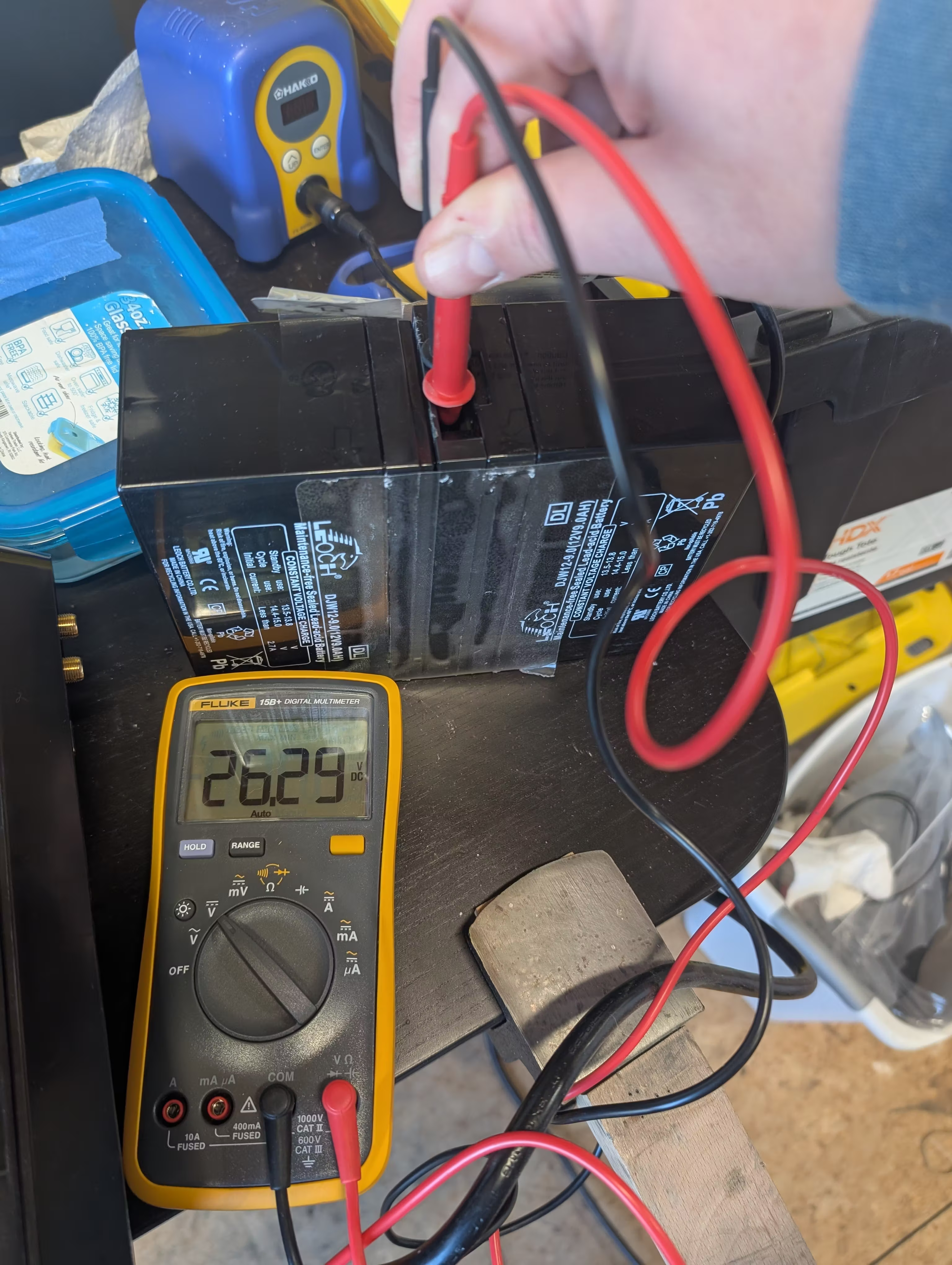
The stock battery configuration uses two 12V 9Ah sealed lead-acid batteries connected in series to provide the 24V system voltage. A quick voltage test confirmed the 24v configuration:

Old battery pack voltage test showing 26.29V on a Fluke multimeterOld battery pack voltage test showing 26.29V on a Fluke multimeter

The meter shows 26.29V on the old pack - close to nominal, but the battery runtime had dropped to a measly 5 minutes under light load.

The Solution

Rather than purchasing a wholly new UPS, I went into the local autoparts store to look for the cheapest 12v pair I could buy. The 12V 18Ah sealed lead-acid batteries I found are double the amp-hour capacity of the stock batteries. By trading in the old batteries, I avoided paying the core fee on the new ones.

New ES17-12 batteries from O'Reilly Auto Parts displayed with old battery cores and Super Start battery boxNew ES17-12 batteries from O'Reilly Auto Parts displayed with old battery cores and Super Start battery box

The catch? The new batteries are physically larger than the stock batteries and won’t fit inside the UPS case. The solution was a cheap external battery box which provides plenty of room for the larger cells.

Installation

The installation process is straightforward if you’re comfortable working with low-voltage DC wiring:

Preparing the External Battery Box

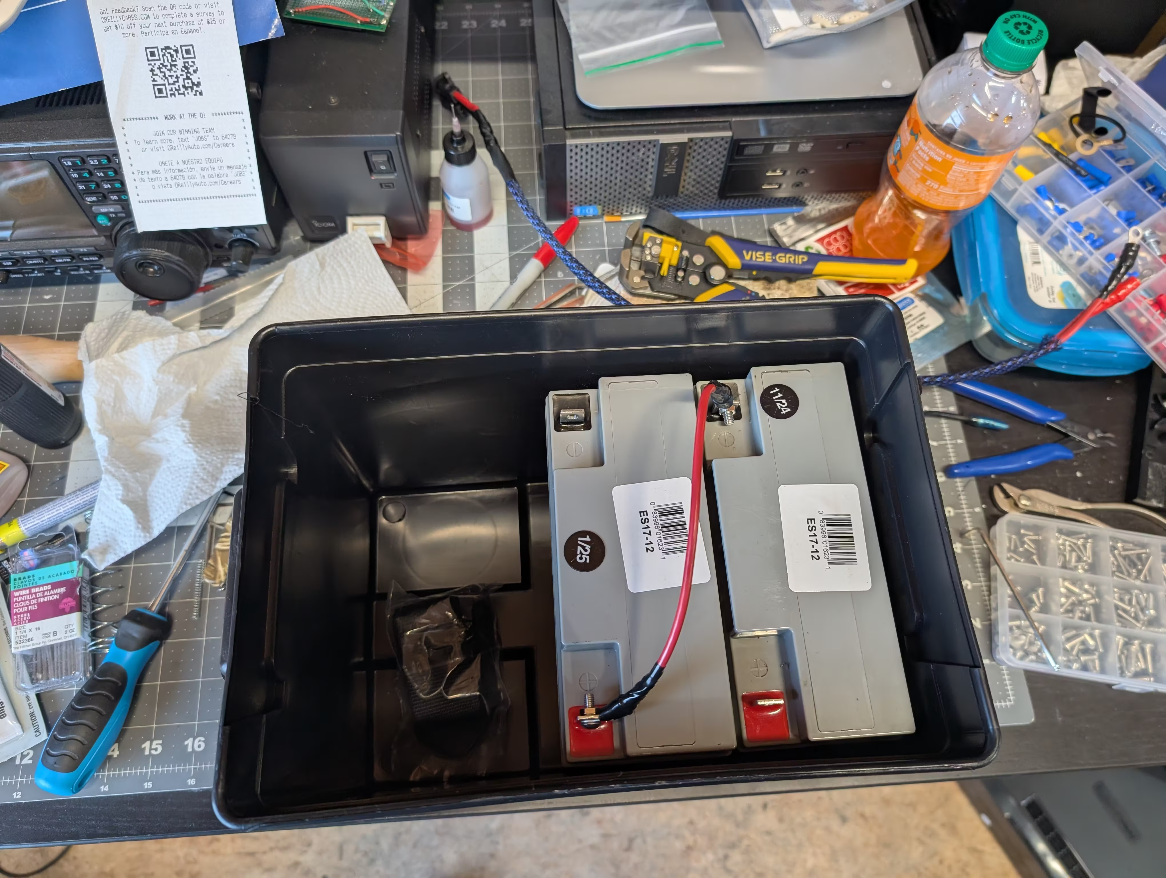
The first step was wiring the new batteries in series to produce the required 24V. As you can see, there’s plenty of extra space in the box for future expansion:

ES17-12 batteries installed in external battery box with initial series wiring showing extra space for future expansionES17-12 batteries installed in external battery box with initial series wiring showing extra space for future expansion

The batteries are connected in series - positive terminal of the first battery to negative terminal of the second battery. The remaining positive and negative terminals become the output that connects to the UPS.

Routing the Leads

After completing the internal wiring, I routed the output leads through the side port of the battery box and protected them with some nylon wire loom:

Completed battery box wiring showing series connection with blue wire loom protecting the output leadsCompleted battery box wiring showing series connection with blue wire loom protecting the output leads

Testing and Connection

Before connecting to the UPS, I verified the voltage output from the new battery configuration:

Voltage test of new battery configuration showing 25.48V on Fluke multimeter, confirming proper assemblyVoltage test of new battery configuration showing 25.48V on Fluke multimeter, confirming proper assembly

The meter shows 25.48V - right where it should be for a freshly assembled 24V battery pack. With voltage confirmed and polarity verified, I connected the leads to the UPS and powered it on.

Results

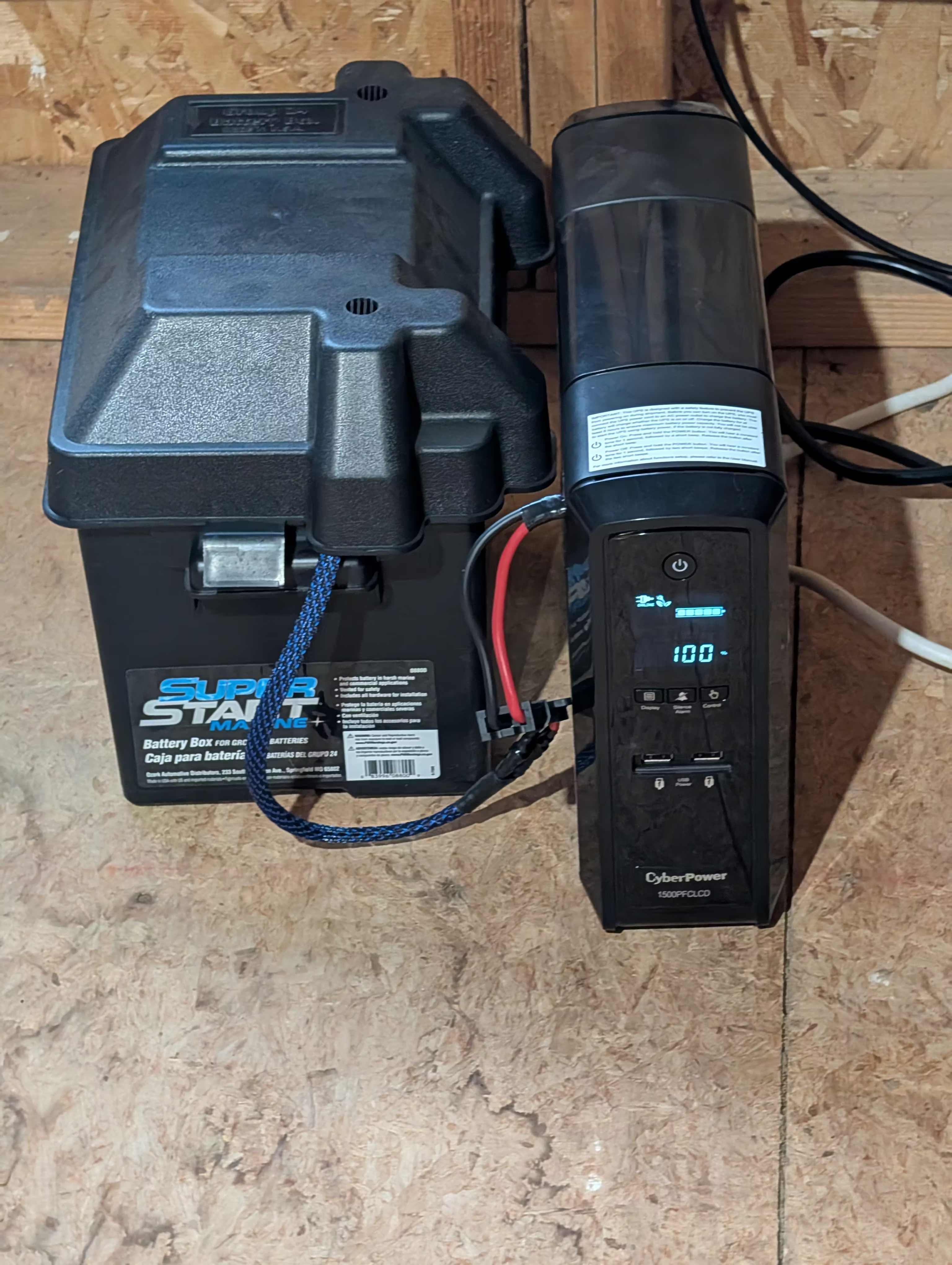
Completed installation with external battery box connected to Cyberpower CP1500PFCLCD UPS via wire loom protected leads, UPS display showing 100% chargeCompleted installation with external battery box connected to Cyberpower CP1500PFCLCD UPS via wire loom protected leads, UPS display showing 100% charge

The UPS immediately recognized the new batteries and began charging. The results exceeded expectations:

  • Battery runtime estimate jumped from approximately 5 minutes to approximately 70 minutes
  • The UPS recognized and began charging the new batteries without issue
  • The external battery box has additional room for another pair of batteries if I choose to expand capacity further in the future

Tradeoffs

There is one notable drawback to using significantly larger capacity batteries:

  • The UPS takes considerably longer to fully charge the 18Ah batteries compared to the original 9Ah pack. This is expected given the doubled capacity, but it’s worth noting if you experience frequent power outages.

Conclusion

For the cost of the batteries and a battery box, I’ve extended the life of an otherwise functional UPS and more than doubled its runtime. While this approach sacrifices the compact form factor of the original design, it provides excellent value and leaves room for future expansion. The longer charge time is a minor inconvenience compared to the extended runtime during outages.

Installing Windows 10 in Qemu with KVM

These are the steps I arrived at in order to install a Windows 10 Guest on an Ubuntu 18.04 host using virt-manager to install a Qemu VM with KVM acceleration and VirtIO drivers.

Prerequisites

Create a directory to work in and install the tools we will need. The virtio-win ISO image contains the drivers we will need in order to make Windows bootable.

1
2
3
4
mkdir windows
cd windows/
sudo apt-get install virt-manager
wget https://fedorapeople.org/groups/virt/virtio-win/direct-downloads/archive-virtio/virtio-win-0.1.160-1/virtio-win-0.1.160.iso

You will also need to copy your Windows 10 installer ISO into your windows/ directory.

Disk Setup

This creates a blank image that will be attached as a virtual hard drive to the Windows instance. We use qcow2 because it supports some nice extensions above those on the raw format, like thin provisioning of storage.

1
qemu-img create -f qcow2 windows_10_x64.qcow2 75G

Creating the VM

Call virt-install to create the VM.

1
2
3
4
5
6
7
8
9
10
11
12
13
virt-install \
--name=windows10 \
--ram=2048 \
--cpu=host \
--vcpus=2 \
--os-type=windows \
--os-variant=win10 \
--disk path=windows_10_x64.qcow2,format=qcow2,bus=virtio \
--disk en_windows_10_enterprise_x64_dvd_6851151.iso,device=cdrom,bus=ide \
--disk virtio-win-0.1.160.iso,device=cdrom,bus=ide \
--network network=default,model=virtio \
--graphics vnc,password=trustworthypass,listen=0.0.0.0

Verify the running VMs with the virsh command:

1
2
3
4
5
~/windows $ virsh list
Id Name State
----------------------------------------------------
4 windows10 running

Connecting to the VM

Now that the VM is running, you need to connect to it and install Windows. VNC to the host machine on port 5900 using the password you specified in the virt-install command. You did change that password, didn’t you?

On Mac OS you can use open to call the built in VNC client.

1
open vnc://<host>:5900

Windows Install

There will be a few extra steps to install Windows above and beyond a normal install. Because the accelerated VirtIO drivers required to interface with the virtual disk controller are not bundled with Windows, we need to load them into the installer before it will be able to talk to the virtual hard drive.

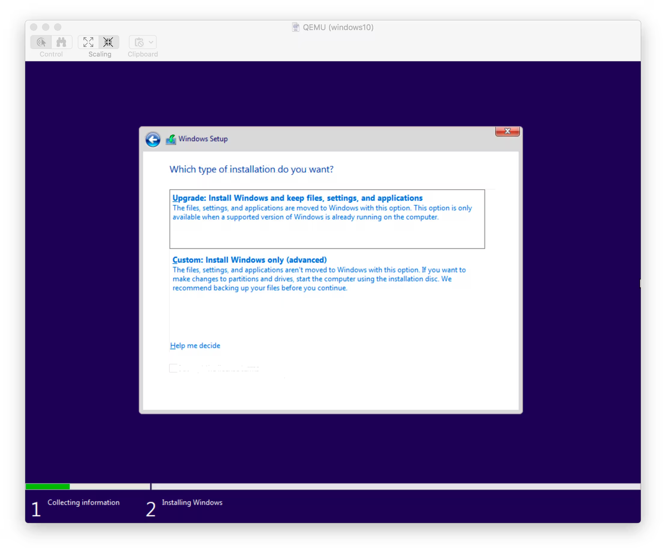
When asked to do an Upgrade or a Custom install, select Custom Install.
Windows Setup screen showing Custom Install option selectedWindows Setup screen showing Custom Install option selected

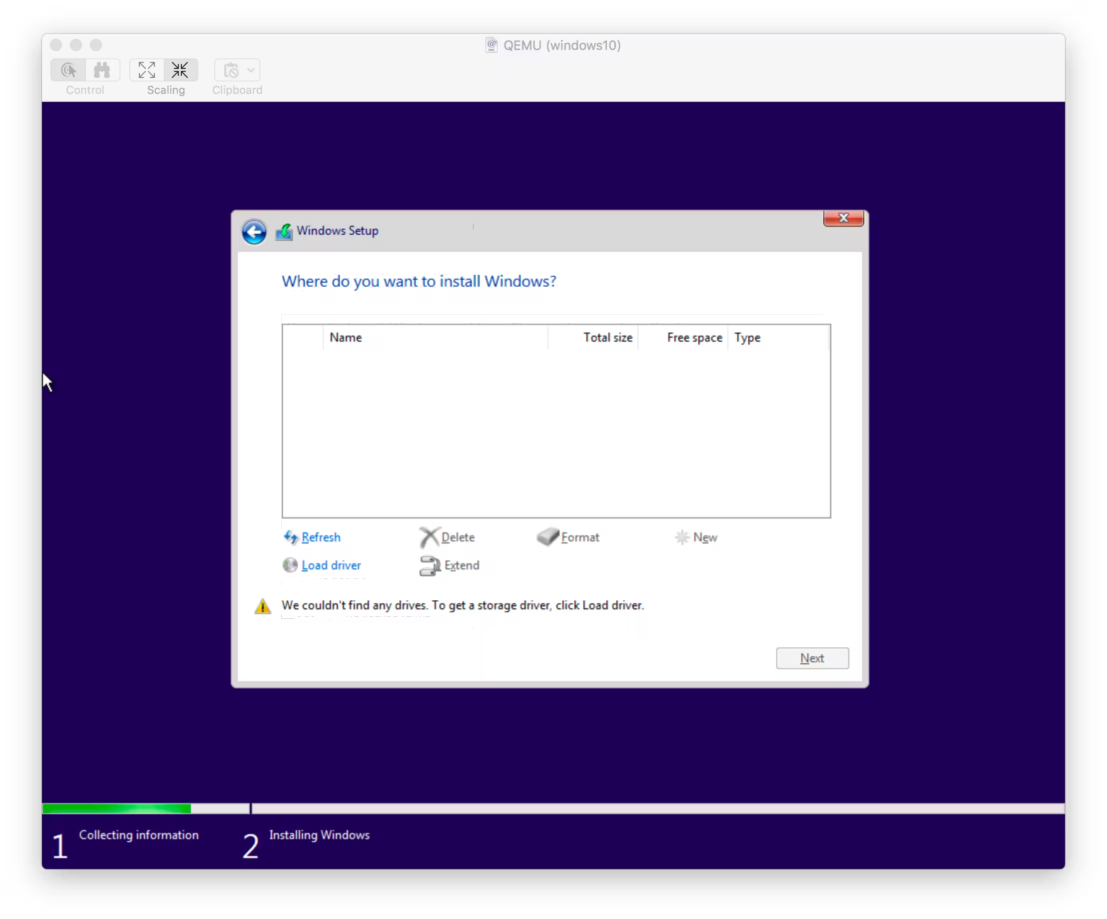
Select Load Driver to point the installer to your driver file.
Windows Setup disk selection screen with no drives found, highlighting the Load Driver buttonWindows Setup disk selection screen with no drives found, highlighting the Load Driver button

Navigate to E:\viostor\w10\amd64
Browse for Folder dialog showing viostor driver folder structure with w10/amd64 directory selectedBrowse for Folder dialog showing viostor driver folder structure with w10/amd64 directory selected

There should only be one option, the VirtIO SCSI Controller.
Driver selection screen showing Red Hat VirtIO SCSI controller driverDriver selection screen showing Red Hat VirtIO SCSI controller driver

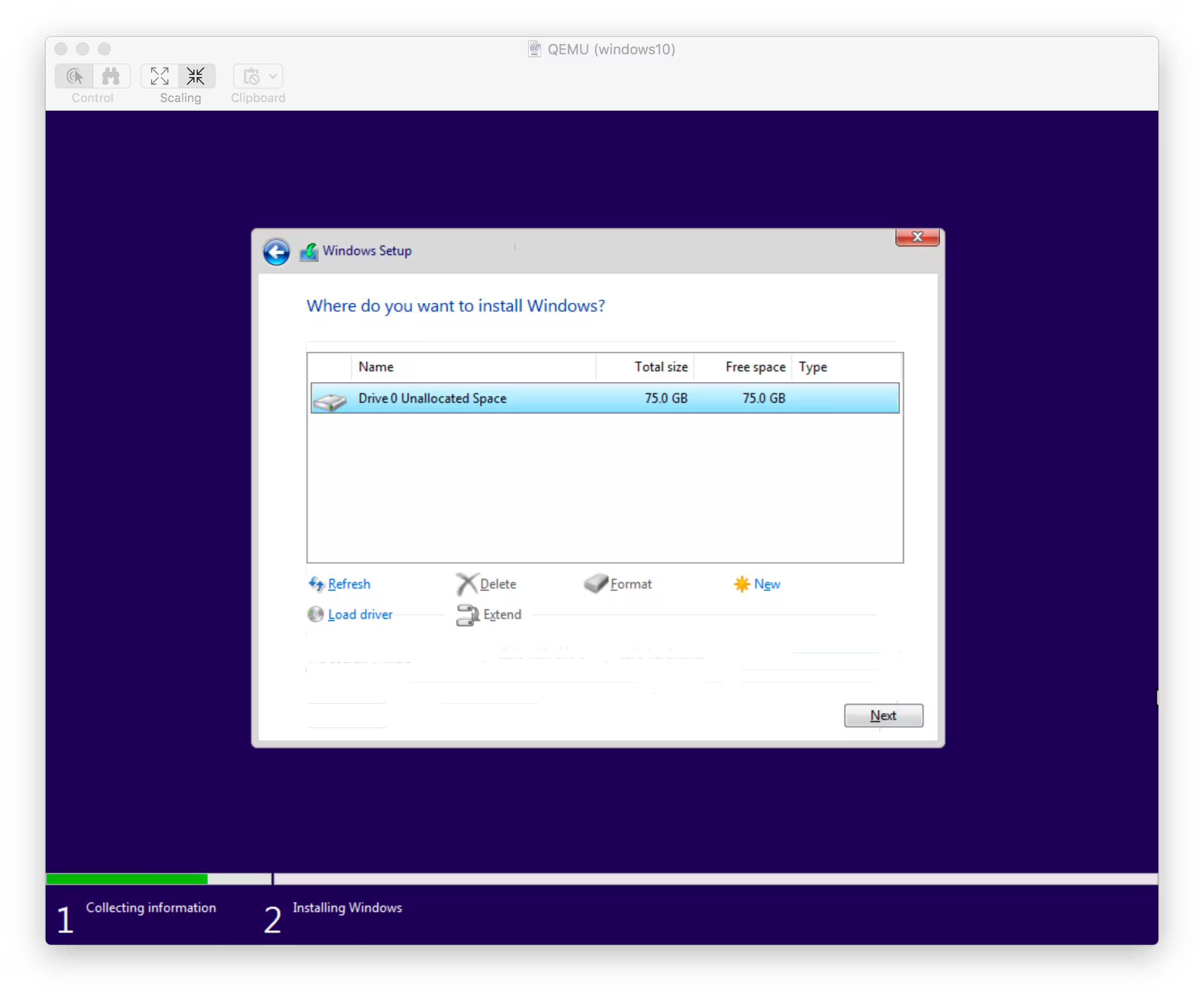
The installer should now see your virtual disk. Hit next to let Windows automatically partition it.
Windows disk selection screen now showing Drive 0 Unallocated Space with 75.0 GB availableWindows disk selection screen now showing Drive 0 Unallocated Space with 75.0 GB available

Next steps

Once the installer finishes and you get into Windows you may want to do a few more things

  • Install the other drivers on the virtio-win ISO (network, etc…)
  • Apply Updates
  • Enable RDP

Connecting the First Alert Zcombo Smoke Alarm to Home Assistant

After some trial and error, I was able to connect my First Alert Zcombo Alarms to Home Assistant via a USB Aeotec Z-Stick.

Ensuring the device is excluded

If the device was previously added to the network, or if you just want to be sure you are starting from scratch, start by excluding the device.

  • Slide the battery tray out on the alarm.
  • In the Home Assistant Z-Wave console, press the Remove Node button.
  • While holding the the Test button on the alarm, slide in the battery tray. Continue to hold the Test button for a few seconds, releasing after the first beep
  • Wait 10-20 seconds for the Alarm to beep a second time. This indicates the exclusion worked.

Joining the network

The procedure to add the device back to the network is very similar.

  • Slide the battery tray out on the alarm.
  • In the Home Assistant Z-Wave console, press the Add Node button.
  • While holding the the Test button on the alarm, slide in the battery tray. Continue to hold the Test button for a few seconds, releasing after the first beep
  • Wait 10-20 seconds for the Alarm to beep a second time. This indicates the network join has succeeded. If you hear three bursts of three tones, this is an error and you should exclude the device and try again.

If you are adding multiple devices, I recommend setting a descriptive name for the device just added in the entity registry before adding more devices. Without setting a custom name right away, you will end up with multiple devices with the same name which will be difficult to sort out later.

Healing the network

The Zcombo devices are somewhat unique in the sense that they do not seem to support waking up on an interval to report their status. Most battery operated Z-Wave devices can be configured to wake on interval but I have yet to find a way to make it work for Zcombo. This lack of wake support seems to be corroborated by other people on the internet.

However, if you want to heal the network or manually force the device to wake up and report its status, this is possible. Simply repeat the battery slide/Test button procedure as before.

  • Slide the battery tray out on the alarm.
  • If you want to heal the network, you can press the Heal Network button in the Home Assistant Z-Wave console. If you are not concerned with healing and just want the device to report it’s status, you do not need to press any Home Assistant buttons.
  • While holding the the Test button on the alarm, slide in the battery tray. Continue to hold the Test button for a few seconds, releasing after the first beep
  • Wait 10-20 seconds for the Alarm to beep a second time. This indicates the device has woken up.

If all has gone well, the devices status in Home Assistant will change to Initializing (Session). This will persist for 15-30 seconds, then the device will switch to the Sleeping state.

ESP8266 and Micropython

In traditional “cheap electronics” fashion, the unit i’ve purchased is verbosely marketed on Amazon as

HiLetgo 2pcs ESP8266 NodeMCU LUA CP2102 ESP-12E Internet WIFI Development Board Open source Serial Wireless Module Works Great with Arduino IDE/Micropython

In more helpful terms:

  • ESP-12E is the SMT module on the board, which consists of an ESP8266 MCU
  • CP2102 is the USB to UART chip on the board
  • NodeMCU is the firmware that comes on the board, which contains and embedded LUA interpreter

Flashing MicroPython

The tutorials on the MicroPython site list a flashing command similar to the one below. However, those commands did not work for me. A helpful Amazon reviewer pointed out setting --flash_mode dio is required in order to correctly flash this particular board.

Reportedly it is also important to erase the flash before writing a new image. This overwrites all blocks with 0xFF bytes.

1
2
esptool.py --port /dev/ttyUSB0 --baud 115200 erase_flash
esptool.py --port /dev/ttyUSB0 --baud 115200 write_flash --flash_size=detect --flash_mode dio 0 esp8266-20171101-v1.9.3.bin

After flashing is complete, open the serial REPL:

1
screen /dev/ttyUSB0 115200

Or access the REPL through the python app rshell:

1
2
pip3 install rshell
rshell -p /dev/ttyUSB0 -b 115200 repl

Micropython REPL Keyboard Shortcuts

Once in the REPL, there are a number of useful keyboard shortcuts:

  • Ctrl-A on a blank line will enter raw REPL mode. This is like a permanent paste mode, except that characters are not echoed back.
  • Ctrl-B on a blank like goes to normal REPL mode.
  • Ctrl-C cancels any input, or interrupts the currently running code.
  • Ctrl-D on a blank line will do a soft reset.